Specify combined-cycle steam turbine’s rotors for daily start, stops
As published in Energy-Tech Magazine:
By Stephen R. Reid, PE
Combined cycles are expected to cycle on and off more frequently than conventional fossil-fired units. To ensure reliable service, plant owners and developers must carefully evaluate cycling criteria when specifying or purchasing steam turbines for these facilities. Detailed specifications must be developed to ensure the steam turbine chosen could respond rapidly and operate reliably under these conditions.
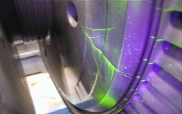
The design criteria for the steam turbine must include optimum materials, detailed stress and low-cycle fatigue (LCF) analysis, verification testing, fracture mechanics analysis and advanced non-destructive examination (NDE) testing.
Rotor crack initiation factors
Every start, stop and load change decreases the net LCF life of a steam turbine. Mitigating fatigue-related problems means reducing the potential for crack initiation and limiting subsequent crack growth from inherent component flaws. Engineers should first evaluate which operating procedures can be modified or optimized to reduce LCF damage. Second, product design enhancements must provide the optimum turbine for the application and resulting duty cycle.
Thermal stresses
Lowering the temperature differential between metal turbine components and the steam flow is an important goal of all operational changes to be considered. Thermal-related stresses have a major influence on crack initiation in the high-pressure (HP) and reheat turbine (IP) sections. There are several ways to reduce thermal stress, including: (1) extending the full-load ramp-up time during start-up and load changes, (2) limiting the steam’s mass flow rate during start-up, (3) extending soak times and (4) modifying the ramp-down rate during shutdowns.
Of these, strong focus should be placed on the shutdown cycle. Reasons: (1) rapid start-up and load-change capability is an important aspect of the station’s design because of the stringent demands of peaking power operation, and (2) changes in the shutdown cycle are just as effective for reducing the total stress range as those made to the start-up cycle.
One option the writer believes should be considered is rapidly going from steady-state operation to the no-load condition. The goal is to minimize the time period in which the turbine operates with both a high mass-flow rate and low steam temperatures. Of course, this option is dependent on the actions of the power pool’s load dispatcher. The shutdown cycle chosen is based on a thermal stress analysis, which in general should reveal gradually reducing load before shutdown – known as forced cooling – can decrease turbine life significantly. In fact, rapid shutdown from the full-load or steady-state condition can double the turbine’s expected life compared to forced cooling options.
Centrifugal stress
In general, the combination of thermal and centrifugal stresses plays a major role in LCF damage to the high pressure and intermediate-pressure turbines. In contrast, centrifugal stress acting alone is the primary cause of LCF damage in low-pressure turbine and generator rotors. Choosing components designed for minimal centrifugal stress is a key aspect of the utility’s design specification, evaluation and optimization effort.
By studying the results of finite-element analyses, the engineer can identify where peak centrifugal stresses exist for various turbine rotor component designs. During a different project, finite-element analysis revealed that the filleted contours of one conventional LP rotor disk would exhibit high peak stress concentrations in the planned operating mode. In this case, the author virtually eliminated the stress concentrations by specifying a rotor disk design with smoother, more gradual contours (see Figure 2).
A similar exercise will help identify the optimal design for the low-pressure rotor’s last-stage blade-attachment zone – an area where peak centrifugal stresses dominate and thermal stresses are virtually non-existent. Design of the last-stage blade area is crucial because LCF damage tends to be greatest here. Thus, all prospective turbine vendors should be required to submit finite-element analyses showing their machine’s peak stresses in this area.
Extreme care is important when comparing peak-stress analyses from different turbine suppliers.
First, recognize that stresses greater than a given material’s yield strength must be corrected to reflect the true plastic strain (see Figure 3). The writer would expect all of the last stage blade-attachment designs will feature peak stresses higher than the rotor material’s yield strength. In all cases, based on common stress/strain behavior for LP rotor materials, the true plastic strain is well above the fictitious value that would be reached if the effects of plasticity are ignored. Thus, well-established methods of correcting for plastic strain, such as Neuber’s rule, should be understood and applied. The explanation of these methods goes beyond the scope of this article. However, ignoring these methods might yield gross errors in predicted LCF damage and component life.
Other factors that must be studied carefully when comparing peak-stress analyses supplied for different designs include: (1) the effect of blade-root-to-groove tolerance on peak stresses, (2) the type of finite element applied, (3) the effect of blade and root-groove boundary conditions, (4) mesh refinement and (5) the number of nodes per element. Overall, you must determine the effects of any differences between finite-element analysis methods and assumptions used by different manufacturers.
In addition to the LCF and creep-data information manufacturers provide based on standard laboratory tests of sample specimens, some OEMs also offer verification testing of the actual root-groove configuration. Although not universally applied by all, this test is the best available for evaluating component designs, because peak stresses do not have to be approximated and the root-to-groove interface conditions are incorporated.
Creep
In addition to cycling stress, long-term creep also plays a major role in the initiation of cracks in HP and IP turbines. Creep rupture characteristics for a given rotor material can be analyzed by studying the material’s Larson-Miller stress-rupture curves (see Figure 4). The Larson-Miller parameter (LMP) correlates allowable rotor stress to exposure time, temperature and material.
Given a known steady-state value for maximum stress, the fractional life reduction for critical components can be found by using the LMP chart to identify a material’s LMP for creep rupture.
Assuming the resultant exposure time for creep rupture is greater than the plant’s design life, the fractional damage can be estimated by the ratio of the plant’s design life to creep-rupture time. In some cases, the turbine manufacturer might include creep data as part of the LCF design charts.
Crack propagation analysis
The presence of a small crack does not necessarily mean a turbine has reached the end of its useful life. Therefore, the factors that cause a crack to grow to a critical size also must be studied.
Every turbine component has flaws that are inherent in the forging and fabrication process. In many cases, the flaws are too small for accurate evaluation by existing NDE methods. Thus, linear-elastic fracture mechanics (LEFM) criteria should be incorporated into the turbine specifications. These requirements dictate that manufacturers must prove any indication detected in the turbine will not grow to critical crack size within a given duty cycle.
For steam-turbine rotor designs, several areas along the rotor’s centerline and high-stress subsurface locations near the rotor’s perimeter will need to be evaluated using Linear Elastic Fracture Mechanics (LEFM). The specification should set very conservative criteria for these analyses to yield conservative estimates for crack growth.
By definition, stress intensity is the magnitude of stress at a crack’s tip. Note – the stress intensity at any given flaw is affected by the flaw’s geometry. For example, the stress intensity of an elliptical flaw is greater than that of a circular flaw. To add conservatism to the crack-propagation analysis, it is recommended that all flaws be considered elliptical, with an aspect ratio of 5-to-1. In addition, suppliers should be required to consider the effects of flaw-to-flaw and flaw-to-surface interactions.
This means flaws that are close together are treated as if they have already spread to form a single flaw. Flaws located inside the rotor, but near the surface, are treated as if they have already reached the surface. Note – flaws on a material’s surface have increased crack-growth characteristics and lower critical crack sizes.
Because the stress pulling a crack tip apart varies as a crack grows, adjustments must be made in this stress value as part of the fracture-mechanics evaluation. Several crack-growth analysis codes can help with this calculation, including the “SAFER” program developed by EPRI.
With proper due-diligence design review/evaluation of OEM turbine options, coupled with thorough and detailed specifications, long-term, trouble-free cycling operation will be achieved.
Material optimization
Regardless of the turbine supplier, power producers can ensure conservatism in the rotor design by specifying materials optimized for LCF and creep resistance. Example: metals with high ductility will have larger critical crack sizes compared to less ductile materials. This translates into longer component life. A material’s impact energy is one measure of ductility. A material’s fracture toughness, which determines critical crack sizes, can be approximated directly if it’s resulting from impact energy.
Another materials-related property that should be considered is the Fracture Appearance Transition Temperature (FATT). This is the temperature at which a material transitions from brittle to ductile behavior. Specify materials with the lowest FATT possible to ensure the best possible toughness characteristics during startup with minimal pre-warming requirements.


