Turbine Water Induction Protection Systems
The accidental introduction of water in any part of a steam turbine can cause serious damage requiring extended outages to make costly repairs. A proliferation of such incidents in the electric power generation industry prompted the American Society of Mechanical Engineers (ASME) Standards Committee to develop a uniform set of design criteria to alleviate the problem. With the recent update of ASME Turbine Water Induction Protection (TWIP) standards and the continued focus on fossil plant reliability, TWIP system upgrades have gained increased focus as capital improvement projects.
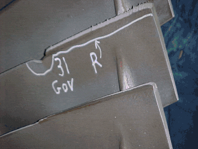
TG Advisers has identified many clients that have experienced major water induction turbine outages, resulting in millions of dollars of damage. In the extreme case, full blade replacements and rotor straightening technologies have been employed to return the unit to service. Forced outage durations can extend to 6 months or greater. The below photo was taken after an LP heater level control failure on a 1960’s vintage General Electric LP rotor design. Extensive LP blade damage resulted in full last stage blade replacements.
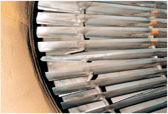
IN MORE SEVERE WATER INDUCTION INCIDENTS, TURBINE ROTORS HAVE BEEN PERMANENTLY BOWED. REPAIRS IN THESE CASES COULD BE AS EXTREME AS FULL ROTOR REPLACEMENT OR A COMBINATION OF WELD REPAIR OR HEAT TREATMENT OF THE BOW.
Causes of Water Induction
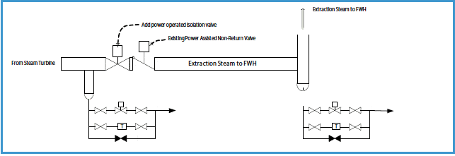
There are many sources of water induction in a steam turbine. The following is a list of the most common sources addressed in the ASME TDP-1 standard:
- Motive steam systems
- Steam attemperation systems
- Turbine extraction/admission systems
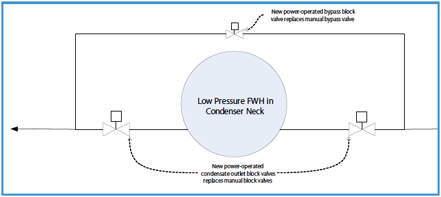
- Feedwater heaters
- Turbine drain systems
- Turbine steam seal systems
- Start-up systems
- Condenser steam and water dumps (steam bypass)
- Steam generator sources
Generating units that were designed and built prior to the development of the design criteria are consequently at risk.
To properly assess the status of steam cycle piping systems with regard to the current design criteria, a Steam Turbine Water Induction Protection Unit Checklist is used. Plant and engineering personnelfamiliar with the plant configuration can complete input for the program. The analysis then compares plant equipment to the ASME standards and identifies where additional protection schemes are required.
The resulting vibratory response of the blade to this harmonic excitation will dictate whether one or more of the blade natural frequencies must be tuned away from harmonics of running speed. For blade modes that cannot be tuned, it is necessary to keep the resulting vibratory stresses below the endurance limit of the respective materials. Figure 2 provides an example Campbell Diagram which illustrates the number of modes that are typically tuned for a last stage nuclear blade.
It is crucial to recognize the loss of blade material, from erosion or other causes, which can significantly alter a blade or groups vibratory response away from design; and, perhaps reduce or eliminate margins from multiples of running speed. It is rarely a reasonable course of action to do nothing and leave severe erosion untouched.
Figure 3 shows a silver solder and stellite repair in progress which was completed by a major U.S. utility. The repair restored the original blade geometry.
