Overview.
As published in Energy-Tech Magazine:
By Stephen R. Reid, PE
Introduction
Control and governor valves operate under severe service conditions. Exposure to high temperatures, erosion, water induction and low- and high-cycle fatigue can significantly reduce valve life. Valve seat and/or stem erosion due to exfoliation of boiler particles during starts and low load operation is usually the first issue most operators must address. Repairs for erosion damage are well defined and easily managed during valve overhauls. However, accumulating damage due to control/governor valve seat interference fits is often overlooked. A compromised interference fit can lead to significant valve leakage and possibly catastrophic seat failure. This article provides background on the issue, findings from a case study and guidance on evaluating the seat fit area.
Background
Figure 1 illustrates a common control valve seat fit configuration. In addition to an interference fit, the seat is pinned to the valve body to provide anti-rotation and fixity during operating transients.
This design has provided long-term reliable operation on units worldwide. However, if the seat has never been replaced, long-term creep relaxation will eventually reduce fit contact, particularly during shut down and load swing transients. This can lead to increased leakage past the seat and progressive erosion of the fit interface, further exacerbating the issue.
If this mechanism of creep relaxation and erosion continues, the rate of steam leakage will increase. In extreme cases, a unit can roll off a turning gear just from steam passing through the back fit area of the valve seat. This condition is often misdiagnosed as valve seat and plug leakage.
In addition, if the pins are compromised, loss of the interference fit during transient operation might result in catastrophic seat failure.
Case study
TG Advisers was retained to assist in a root cause of a valve seat failure in a supercritical 3,500 psia/1,000°F/1,000°F unit. The seat, original to the unit, was found in several pieces during an inspection to investigate a hammering noise emanating from a control valve. Inspection of the failed parts revealed evidence of erosion on the seat interference fit and failed pins. The goal of the TG Advisers investigation was to determine if long-term creep relaxation of the fit, combined with erosion and compromised pins, was a plausible cause for the failure.
Relaxation of the valve seat to body interference fit was evaluated using a Larson Miller Parameter (LMP) analysis approach. The LMP relates fit stress/strain changes to temperature and time.
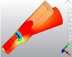
Stresses in the valve body and seat areas were determined using the finite element analysis (FEA) model shown in Figure 2. Such a model enables determination of the required stresses and temperatures.
Estimating the loss in interference fit over time must consider the large data scatter associated with creep relaxation data. For the test case, using a range of 20 percent to 55 percent loss in shrink fit for the operating period was deemed reasonable. Erosion, which reduces the contact area between valve body and seat, has an additional degrading impact above and beyond the estimated creep effect.
During steady state operation, there is minimal temperature differential between the valve body and seat. However, during start-ups and shutdowns, temperature differences can vary significantly.
During shutdowns or load reductions, the seat, due to its direct contact with the steam and relatively low mass, cools more rapidly than the valve body. This reduces the interference fit, which is a function of the temperature difference between the parts (cooler seat reduces the fit). If the initial interference shrink fit is reduced due to long-term creep and erosion, it takes less temperature differential during cooling transients for fit to be temporarily lost.
Assuming a 45 percent reduction in initial interference, a temperature difference of only 30°F is required before contact is lost. Review of unit operating data leading up to the event revealed at least one transient that would lead to a temperature difference of that magnitude. Since the seat was found catastrophically failed and there was evidence of pin failure, it was determined that it was likely one or more pins had been compromised prior to the transient. When the shrink fit was lost, the loose seat vibrated into pieces. Loss of interference fit due to a combination of creep relaxation and erosion was confirmed as a probable cause for the seat failure.
Recommendations
Valve seat to body fit assessments should be thoroughly evaluated during major valve outages.
This is especially true of aging units with original seats. Seat fit areas should be visually inspected for erosion damage and signs of operational looseness. Flow testing with a low viscosity fluid can be performed to check for back seat leakage; OEMs will provide instructions on approved flow testing methods. Standard scope should include assessment of all valve seat pins. When pin issues are found, a minor increase in the replacement pin diameter significantly increases pin creep and fatigue life. As a unit with original seats approaches 30 years of service life, contingency plans for control and governor valve seat replacement should be an integral part of the outage planning process.