Stephen R. Reid, PE
President and Principal Engineer
TG Advisers, LLC.
Gas Conversion Projects
Environmental pressures have caused most US power generation owners to reevaluate both short and long term options for their coal generation assets. Retirements, repowering, upgrading emissions control technologies and conversion from coal to natural gas are the main options that are being considered. Natural gas conversion can provide an economical solution for some units in high value regions of the US. Generally, these units are in the 250 MW or lower range and do not provide the cost justification basis for installation of SCR and scrubber technologies which are typically installed on 500 megawatt units or greater. The due diligence process in establishing the project’s costs for fuel conversion must consider the entire plant and not just the boiler conversion hardware.
With the retirement of many coal units and favorable gas price projections, converted units are expected to play a more strategic and operationally flexible role requiring more cycling and run hours. As they will not have the same attractive heat rates of local combined cycle facilities, frequent on-off cycling will be required. During high demand periods, there will also be an expectation to run for extended periods of time reliably. Units under consideration for fuel conversion are typically much older coal assets that most likely were “on the bubble” for many years with maintenance planning budgets that supported near term retirement over long term reliability.
What about the Steam Turbine Generator?
Failure to consider the steam turbine generator in the project budget can make reliability targets a difficult, if not impossible, goal to meet. TGA has found that the associated steam turbine generator often requires major investments to maintain reliability for life extension of the plant. The following section provides an overview of the major concerns that must be considered!
Major Turbine Issues
Rotor Integrity – After 30 to 40 years of operation, rotor flaws (see figure 1) can develop and/or propagate to a concerning size. On high temperature rotors, creep voids can be initiated with extended time, temperature and stress exposure. In addition, rotor materials can become embrittled from temperature exposure will most likely require more frequent inspections, longer startup thermal soak periods or, in some cases, replacement of the rotor itself.

Figure 1 – Example of a rotor inclusion
Turbine Casing and Valve Body Integrity – Almost all casing and valve body cracks initiate and propagate from stop-starts/low cycle fatigue (LCF). This cracking (see figure 2 for examples) usually appears later in a unit’s life when on-off cycles reach 300 to 500 events. With increased cycling, LCF limits will be reached earlier than previous predictions of calendar life. Repair or replacement options will need to be considered when cracking extends more than 25 to 35% of the casings’ thickness.


Figure 2 – Turbine Casing and Valve Body Cracking Examples
Turbine Controls – Control systems typically become obsolete in ~20 years of operation.
Water Induction Protection Systems – Turbine water inductions can cause major internal damage. Exposure for units that are converted will most likely increase after the fuel conversion.
Low Pressure Turbine Blading – The later stages of low pressure (LP) turbine blades operate in a low quality steam environment. Depending on the degree of erosion, replacement may be required. In addition, LP blades are the largest blades on the unit and, as a result, the most highly stressed. On-off cycling can significantly consume the low cycle fatigue life of these blades.


Figure 3 – Examples of LP Blades Water Droplet Erosion and Lasing Lug Cracking
LP Rotor Stress Corrosion Cracking (SCC) –In TGA’s experience, the real question of SCC of LP rotor dovetails is a matter of “When” and not a matter of “If”. In fossil units, TGA has identified this concern as early as 100,000 hours of operation with most units requiring repairs in the 200,000 hour range. These repairs can be costly and require weld repair and new blading.

Figure 4 – Example of LP Rotor Dovetail Stress Corrosion Cracking
High Temperature Turbine Rotor Dovetails – This failure mode is, again, an issue of time, temperature and stress exposure. Dovetail creep or creep fatigue failures as shown in figure 5 become a concern on units with over 250,000 hours of operation.

Figure 5 – Example of a Control Stage Creep Related Failure
Major Generator Issues
Generator Stator and Rotor Windings – Generator windings are designed to operate reliably for approximately 30 years. Extending a unit’s life to meet the gas conversion goals of 20 plus years will most likely require a partial or full rewind prior to or during the extended life period. Figure 5 below highlights a stator end winding connection crack that required a design upgrade to improve long term reliability. Rotor windings, particularly the end turn regions are susceptible to low cycle fatigue, resulting from cyclic start/stops stresses from centrifugal loading and thermal expansion/contraction cycles. Frequently LCF issues affect rotor radial lead pole flexible connections, as well as pole crossover jumpers.

Figure 7 – Stator End Winding Cracking Example
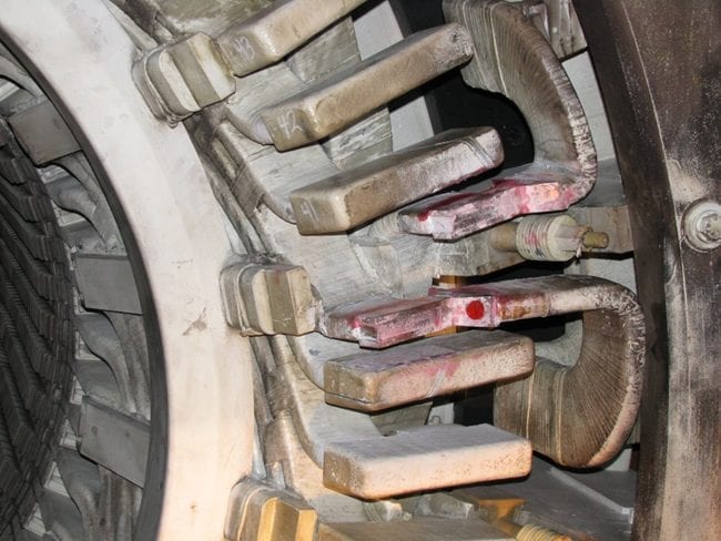
Stator Core Iron – Hot spots in the stator core iron can significantly reduce stator winding life. Shorted laminations are a common finding on older units and should be monitored and if needed, repaired (see figure 8 below). In extreme cases, a full core replacement can be required. If a hot spot is identified near the ends of a core, a partial restack could be the answer.

Figure 8 – Example of Core Lamination Damage (courtesy of Bill Moore PE)Excitation Systems – Many older units have been converted from rotating excitation systems to a static system. This change out has addressed many of the reliability issues frequenting rotating elements. Contingency planning for replacement of an aging excitation and automatic voltage regulator (AVR) systems should be developed.