High temperature steam turbine rotors
Background
New environmental regulations and the installation of renewable energy sources have resulted in many retirements of older legacy steam turbine generating units. Most of these older units have spent the majority of their life in operation “base loaded.” As a result, they have logged significant operating hours with few on/off cycles. Long-term, temperature dependent damage mechanisms of these turbine rotors must be considered to ensure successful operation to the desired retirement dates. This article highlights two case studies and some operational strategies to extend life to the desired retirement date.
Consider high temperature, life limiting mechanisms
HP and IP rotors with material properties similar to ASTM A470 typically operate with steam inlet temperatures of 1,000°F. With time, creep cracks can initiate in highly stressed areas. In addition, the material can suffer significant embrittlement with time, reducing the material ductility that is an important property for remaining life analysis. These mechanisms are at play in the rotor bore and blade attachment sections.
Creep
Creep is a time, temperature and stress dependent mechanism that must be considered for units with a significant number of service hours. For creep cracking, rotor operating temperatures in general must be above 800°F and a significant stress level must be present at all times to be concerning. Creep life targets of 30 years are frequently quoted by OEMs for high temperature rotor designs. Design life is typically determined from a “Larson Miller” curve, which relates time, temperature and stress for crack initiation (see Figure 1). The LMP approach does not account for crack propagation and/or the interaction of creep and fatigue from on and off cycling. The industry has utilized a fracture mechanics approach to assess life once cracks have initiated, and/or to assess pre-existing cracks in high temperature zones of steam temperature rotors.
As noted in Figure 1, there can be a significant scatter of creep material data. The OEMs will add additional safety margins and define a “Design Curve,” which is always lower than the curve produced from the minimum test points. As a result, units usually far exceed their 30-year creep design target. Rotor life is often limited by pre-existing flaws that are developed from the forging process. This is especially true of rotors produced prior to forgings, which were manufactured using vacuum degasing technology (i.e. air melt process).
Embrittlement
Dr. Swami Swaminathan of TurboMet International, while under contract by Electric Power Research Institute (EPRI project 2481-5) performed testing on a retired rotor to support needed materials data for life assessments of service exposed rotors. Testing provided many concerning changes in material properties with time and temperature. A main area of concern was the large degree of rotor embrittlement during the relatively short operating period of less than 200K hours. The degree of embrittlement was quantified by a shift Fracture Appearance Transition Temperature (FATT). The FATT defines the temperature at which the rotor steel exhibits 50 percent brittle and ductile behavior. The resulting critical crack sizes that define the burst condition for a rotor are directly related to the material’s ductility. This parameter is important since it helps to define the required rotor soak period to ensure the material is ductile when it is exposed to high stresses during cold starts.
Swaminathan completed testing in different steady state operating temperature zones at the bore and peripheral locations. The work proved long-term exposure to temperature could increase the FATT by approximately 200°F. Another interesting fact was that embrittlement did not occur in the highest operating temperature zone. Embrittlement was more pronounced in the zone where temperature was in the 800°F range.
As a result of these efforts, pre-existing flaws in rotors have required a more conservative material property boundary condition to assess risks of brittle fracture. In many cases, embrittlement has limited the number of stops and starts and/or has resulted in premature retirement of aging rotors.
Notable case studies
IP rotor embrittlement
As a result of a recent failure of an IP stage 2 dovetail, TG Advisers had an opportunity to evaluate the embrittlement condition on a rotor that logged more than 425K of operating hours. The resulting shift in FATT was significantly greater than expected. The FATT for the stage of concern had increased to more than 600°F which was approximately 300°F higher than a non-embrittled rotor steel of the same chemistry.
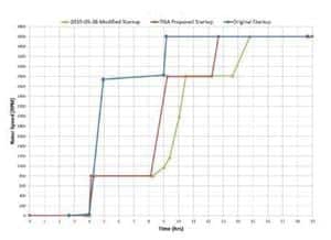
With retirement planned in the near future, the utility decided to remove the stage and evaluate methods to ensure reliable operation until the unit’s retirement date. During the remaining operating window, the unit was expected to have just a few cold starts, which are the most concerning for an embrittled rotor. A decision was made by the evaluating team to assess modifications of the existing rotor cold start procedure to account for the FATT shift. Multiple startup simulations were run varying speed, hold times and ramp rates to ensure high stresses occurred only after the rotor achieved a ductile state. The evaluation also included an assessment of differential expansion, which was significantly changed with longer soak periods.
The results of the analysis proved the embrittled rotors could achieve ductile properties by extending soak periods at lower speeds without detrimentally affecting differential expansion. The plot below shows a potential improvement of 400 percent in critical crack size for a modified cold start. Adapting the revised startup procedures has allowed this utility to stay on track with its retirement plan. Follow up analysis of the actual revised startup practice has shown a close match to the recommended curves.
Control stage failure
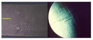
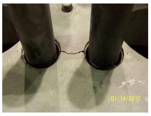
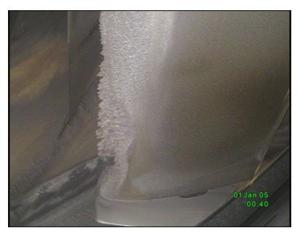
Another notable failure was experienced on an inlet stage of an HP turbine that had accumulated more than 300K hours of operation (see Figure 2).
The failure provided an opportunity for the utility to test larger sections of the control stage disc to determine if a weld repair was feasible. The test program included:
- Rotor Boresonic Tests (MT, UT, visual)
- Material Tests (actual rotor material)
- Tensile Tests (detect creep softening)
- Impact Tests (estimate fracture toughness)
- Accelerated Creep Rupture Test
Testing proved the failure to be attributed to high temperature creep notch sensitivity in the stress concentrated area of the rotor dovetails. Following an assessment of the rotor material properties at various radial locations, a cut line was established and the rotor was built up, stress relieved, re-machined and new blades installed. The repair was successful and the unit achieved its desired retirement date of approximately 10 years after the repair.
Acknowledgements
TG Advisers would like to thank the Consumers Energy team of Matthew T. Helms, Vladimir Trbulin and Mark E. Wittbrodt for their technical support and direction with the HP and IP rotor assessments. TGA also would like to thank Dave Sheasley, Roger Karn and Mark Miller of NRG for the technical support with the HP rotor control stage assessment efforts.

