Overview.
As published in Energy-Tech Magazine:
By Stephen R. Reid, PE, TG Advisers Inc.
Introduction
Torsional vibration resonance can result in significant turbine and generator damage and extended forced outages. The issue of torsional resonance of blades and rotors with the double line system excitation frequency (120 Hz) has led to blade liberation, retaining ring cracking, exciter fan liberation and rotor shaft cracks. Even though the issue is well understood now within the industry, resonance concerns remain.
Reasons for these concerns were related to one or more of the following factors:
– Lack of verification on older designs (many operating units commissioned in the early 1970s have not been analyzed or tested for double line torsional excitation).
– Incomplete or incorrect modeling and assumptions of the turbine generator train after a major upgrade (e.g. LP or generator rotor changes or blade upgrades).
– Increasing trend to reduce torsional verification testing on new technology relying almost exclusively on analysis.
Field testing is an important part of unit verification, which should be pursued any time resonance concerns are identified through an analysis. However, in TG Advisers’ experience, much of the analysis has exhibited modeling errors well outside of the 2009 ISO standard (22266-1) permitted range of 3 percent. In cases of significant error, resonance concerns can go unidentified and put a unit at a high risk of failure. The error in the analysis can be related to the assumptions used to convert a turbine and generator’s actual geometry to a simplified mass and stiffness model. In some instances, the company doing the analysis might not have the geometry of one or more of the components in the system, since they were designed and retrofitted by another company. This article provides an overview of two complementary methods used to verify a design model: finite element analysis and stationary frequency impact testing.
Frequency model development
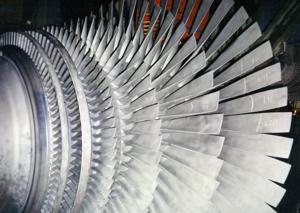
A paramount concern for dynamic analysis is the development of an accurate frequency model. The model must represent the stiffness and mass characteristics of a rotor in the frequency range of interest. Whenever there is an abrupt increase or decrease in rotor geometry, torsional stiffness will increase or decrease. These data ranges must be quantified for acceptable frequency analysis. Figure 1 displays one end of a low pressure turbine rotor that is fully bladed. Figure 2 illustrates the conversion of the same end of the low pressure rotor into equivalent torsional stiffness elements.
To determine the equivalent torsional rotor stiffness model, a finite element analysis can be used. To ensure accuracy, torque is applied to one end of the rotor model while keeping the other end fixed. The two models should match the same angle of twist at various axial locations. Any blade or rotor mass above the stiffness model is added as an additional mass moment of inertia.
Figure 3 represents a complete low pressure blade model used to accurately calculate frequencies up to 180 Hz. In this model, any low pressure blade rows that have frequencies of 150 Hz or less are modeled as dynamic branch elements. These blade modes can couple with the rotor frequencies and produce unique and concerning system frequencies at or near the double line frequency.
Frequency model verification testing
One recommended way to verify analytical models is through stationary frequency impact testing. This method has recently been acknowledged by ISO in a 2009 standard for acceptable torsional frequency analysis for test valves.
It should be noted that an unbladed turbine rotor, unlike a generator rotor, does not change stiffness and frequency when the component rotates. However, when the rotor is bladed, the net stationary and rotating frequencies vary due to centrifugal stiffening (rotating frequency increase) of the blades. Stationary frequency impact tests can be run on both bladed and unbladed rotors. The process used by the writer involves mounting a block on one side of the coupling and impacting the rotor in the tangential direction. The rotor can be on rollers for a torsional test. By moving the accelerometer from different axial and radial positions the impact tests can yield simplified mode shapes, which can be directly compared to the analysis model results.
An example of a low-pressure rotor model analysis and its test calibration results will be described later in the article. Figure 4 provides the calculated mode shape for the low pressure turbine rotor. The resulting impact tested mode shape and frequency is represented in Figure 5, wherein the dotted stick model represents the non-deformed shape, while the solid lines represent the deformed shape. As shown, agreement is excellent.
Multispan system analysis
The multispan analysis model, shown in Figure 6, must include calibrated mathematical models for the remainder of the system, which includes the generator, exciter, jackshafts, spacers and remaining turbines. The generator model, like larger low pressure turbine blades, will have a frequency change with speed because of CF forces on the rotor windings. Temperature also is a factor to be accounted for in any analysis. An increase in temperature will cause a rotor’s shear modulus to decrease, which has a lowering frequency net effect. Temperature effects, based on the experience of TG Advisers, are typically less than 1 Hz and are addressed in the frequency acceptance criteria in the 2009 ISO standard.
By following this simplified turbine calibration analysis for each turbine, element accuracy for the full unit analysis will be greatly enhanced and the confidence level of meeting the new 2009 ISO standard will be significantly increased. This process is acknowledged by many insurance carriers to help support full unit field testing requirements.
Acknowledgements
Many people contributed to the success of the stationary test runs on the rotor. They included the efforts of John Amour and Dr. George C. Kung, who provided invaluable expert technical support throughout these analyses and tests. My appreciation goes out to all who participated in this endeavor.