Dan Skedzielewski
Bill Robbins
Stephen Reid, PE
TG Advisers, LLC.
Background
The potential failure of generator rotor fan vanes and blower blades has been identified as an area for detailed risk assessment in the electric power generation industry. Liberation of fan component has caused catastrophic damage to both the rotor and stator components on a number of units. Industry awareness of this high risk issue has improved, which has led to NDE inspections of all critical fan assembly areas. Many units were previously evaluated by visual inspections only. A visual inspection in most cases is not capable of finding small cracks in fan assemblies.
Generator rotor fans/blowers are critical, highly-stressed components justifying design scrutiny, proper material selection, quality fabrication techniques, and judicious non-destructive examination.
Failure Mechanisms
Generator rotor fans/blowers are subject to both high steady and fatigue stresses during operation. The fan/blower blade itself is highly stressed. The highest stresses in an axial blower are developed in the base of the blade or in the blade root attachment to the blower hub. The highest stresses in a radial flow fan most often occur in the blade attachment to the side shroud or fan ring. These areas represent the most critical locations for NDE and evaluation for each major outage. In addition, a recent study conducted by Electric Power Research Institute (EPRI) noted well over 25 case studies of industry failures in these locations. The report evaluated both fossil and nuclear fan designs.
As expected, there were significant variations in fan geometry existing between manufacturers. The locations of the highest stress areas will vary to some degree as a result. The design process must concentrate on optimizing attachment or fastener geometry. As the fan blade increases in size an increased dovetail size may be used for better distribution of the resulting centrifugal loads. Geometry variations can minimize sharp radius corners and other stress concentrations extending the life of a component significantly. In most cases, small changes in the root contour can make a difference in failure or long term, trouble free operation.
Other common points of crack development and potential failure are a fan wheels inner bore which is typically shrunk on to the generator rotor. Similar to retaining rings, these surfaces are subject to larger interference fits which should periodically be inspected. The failure mechanisms most common to generator fan wheels include: low cycle fatigue, high cycle fatigue, brittle fracture, corrosion and erosion.
Installation Best Practices
For a large percentage of axial blower designs, bolting hardware works to retain individual blades to blower hubs. Bolting is normally tightened to a specific torque and is prevented from loosening utilizing either a locking device or a staking procedure. Failures have occurred due to the loosening of this mounting hardware; therefore to eliminate such failures the following should be adopted during assembly.
- Never reuse locking devices such as lock washers, tab washers and locking strips.
- Prior to an outage, check with the OEM and ensure the correct hardware torque and torqueing technique is being applied.
Axial blower blades which have a threaded or smooth radial attachment can have an adjustable blade angle. Flow may be adversely affected if the wrong angle is selected. This can cause additional blade excitation such as flutter which may ultimately lead to a high cycle fatigue failure. During assembly, ensure the following practices are followed.
- Verify correct method of angle measurement.
- Verify correct base angle setting and +/- angle tolerance.
- A set screw is normally utilized to lock the blade’s angular position. If so, the torque and staking recommendations noted previously would apply.
It is common for both axial and radial blower hubs either to be bolted or shrunk fit to the generator rotor forging. During assembly measure the rotor forging and inner hub diameters to ensure the interference fit is within tolerance. Also, verify the proper heating method and metal temperature targets are being used.
Case Study
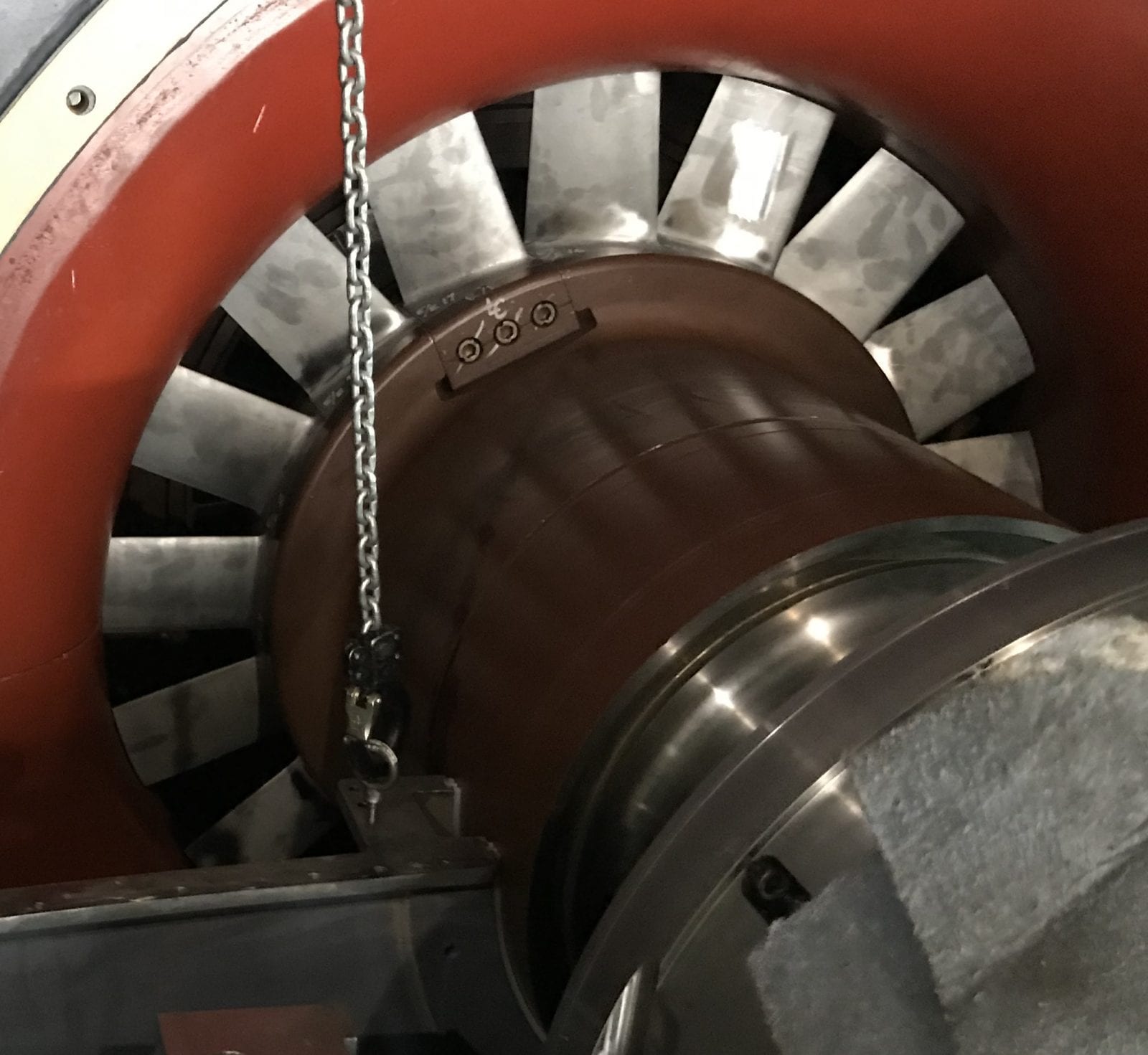
The figure below is a photograph of a generator fan that has its blades welded to an inner hub. The hub is shrunk on to a generator’s rotor shaft end. The highest stress location for this design is at the weld attachment areas. After several years in service, one of the fan blades liberated from the hub caused extensive generator damage. Figure 1 below shows the “as found” hub with the missing blades. Further NDE of the fan wheel identified additional indications at the weld to hub interface (see Figure 2). To eliminate the long term concern over this design, a redesigned fan hub and blade assembly was manufactured from a single forging, thus eliminating the blade weld.
Figure 1 Welded Blade to Hub Fan Assembly

Figure 2 Common Blade to Hub Weld Indications